
Top 10 Telescopic Cylinders for Underbody Applications
Telescopic Cylinders Underbody applications work in tight spaces beneath dump trucks, trailers, and other vocational vehicles. Their nested stages provide long extension from a compact retracted length, but that advantage depends on careful matching. Mounting geometry, stroke, load, operating pressure, and retracted clearance all matter. A cylinder that looks suitable on paper may still conflict with a crossmember or underbody toolbox.
Industry data offers useful context, but not a ready-made product ranking. Grand View Research estimated the global hydraulic-cylinder market at about US$15.5 billion in 2023 and projected continued growth through 2030. Its estimate covers many industries, not underbody telescopic cylinders alone. NTEA’s Work Truck Industry Outlook also tracks conditions affecting work-truck manufacturers and fleets, including equipment demand and chassis availability. These reports point to a broad, active market; they do not replace application-specific engineering checks.
This Top 10 guide compares cylinders by practical criteria: rated capacity, stroke range, stage design, mounting options, material and corrosion protection, serviceability, and manufacturer support. It also considers how a unit may perform through repeated lift cycles, road vibration, dirt, and moisture. Small margins matter. Check the vehicle maker’s requirements and the cylinder’s published specifications before selecting a model. Ratings can use different test conditions, and product listings do not always explain those differences clearly. That is worth questioning. The strongest choice is not automatically the cylinder with the largest force rating; it is the one that fits the available space and duty cycle with a documented safety margin.
What Telescopic Cylinders Do in Underbody Applications
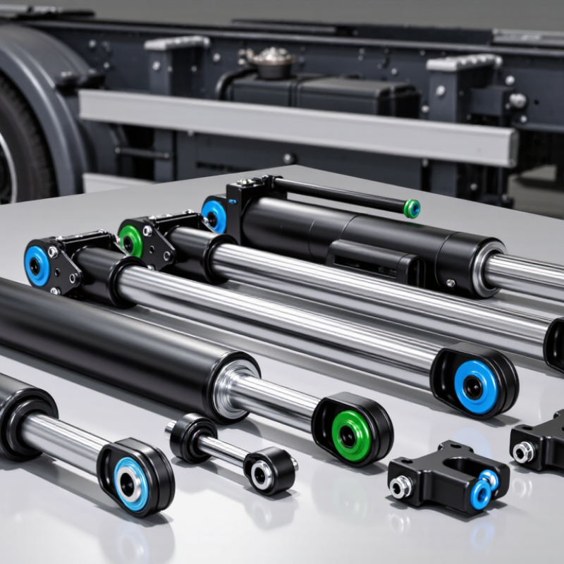
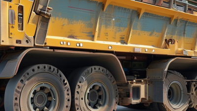
Underbody telescopic cylinders turn compact hydraulic motion into a long, controlled lift. Their nested stages stay short when retracted, fitting beneath truck bodies where frame rails, axles, and crossmembers leave little room. As hydraulic pressure enters the cylinder, the stages extend in sequence and raise a dump body or service platform. The expanding profile is easy to overlook. Yet it shapes the lift path.
Cylinder choice depends on required stroke, load, mounting points, and available clearance. A cylinder’s lifting force can change as its stages extend, so engineers check the full movement range, not just the starting position. It is tempting to size only for maximum lift; that can be a costly mistake. Poor alignment or side loading may wear seals and guides faster. A well-matched unit works with the body’s hinge geometry and helps keep movement steady on uneven ground. It still needs regular inspection. Look for oil leaks, bent components, loose pins, and damaged hoses; small signs can reveal problems before the next lift.
Top 10 Telescopic Cylinders for Underbody Applications - What Telescopic Cylinders Do in Underbody Applications
This comparison covers common telescopic-cylinder configurations and application setups for vehicle underbodies. The ranking is a practical overview, not a brand or model list. Stage count, mounting, and operating action should be selected for the vehicle geometry, load, stroke, and hydraulic system.
| Rank | Configuration | Typical action and stages | Common underbody application | What it does | Key selection consideration |
|---|---|---|---|---|---|
| 1 | Single-acting multi-stage hoist cylinder | Hydraulic extension; gravity or load-assisted retraction. Multiple nested stages. | Underbody dump hoists and tipping trailers | Provides a long lifting stroke from a relatively short retracted package. | Check stage sequence, available mounting space, load stability, and reliable retraction conditions. |
| 2 | Double-acting multi-stage cylinder | Hydraulic extension and retraction; multiple stages. | Applications requiring powered lowering or controlled return | Uses hydraulic pressure to move the cylinder in both directions. | Account for additional hydraulic connections and the circuit requirements for both directions. |
| 3 | Front-mounted telescopic hoist arrangement | Usually a multi-stage cylinder; action depends on the system design. | Dump bodies with a cylinder mounted near the front of the chassis | Raises the body from a forward mounting point to produce a tipping motion. | Verify body pivot geometry, cylinder angle, and clearance throughout the full tipping arc. |
| 4 | Underbody-mounted hoist arrangement | Typically a compact, multi-stage cylinder; action varies by design. | Vehicles where the hoist is installed beneath the body or chassis area | Converts cylinder extension into body lift while keeping the unit within the underbody envelope. | Assess ground clearance, chassis interference, service access, and protection from road debris. |
| 5 | Low-profile multi-stage cylinder | Single- or double-acting; stage count is selected to suit the required stroke and envelope. | Chassis installations with restricted vertical space | Delivers useful extension while fitting into a limited retracted height. | Compare collapsed length and extended length, and check the entire motion path for obstructions. |
| 6 | Three-stage telescopic cylinder | Action may be single- or double-acting; three nested stages. | Medium-stroke vehicle hoists and compact tipping systems | Balances extended reach with a shorter retracted length than a comparable single-stage cylinder. | Confirm that the available force at each stage meets the load requirement across the stroke. |
| 7 | Four-stage telescopic cylinder | Action may be single- or double-acting; four nested stages. | Installations needing a long stroke from a compact retracted package | Extends through successive stages to achieve a long overall travel. | More stages require careful attention to stage sequencing, seals, maintenance, and load distribution. |
| 8 | Multi-cylinder synchronized hoist setup | Two or more cylinders; synchronization depends on the hydraulic and mechanical design. | Wide bodies or lifting arrangements that use more than one lifting point | Shares lifting work across multiple points to support the body during movement. | Plan for synchronization, structural load sharing, and the consequences of uneven movement. |
| 9 | Telescopic cylinder with articulated mounting | Usually mounted with pivots or joints to accommodate changing angles. | Tipping bodies whose cylinder angle changes during lifting | Allows the cylinder to follow the changing geometry between the chassis and body. | Prevent side loading by checking pivot alignment and articulation over the full operating range. |
| 10 | Protected or shielded telescopic cylinder installation | Cylinder action and stages are selected for the lifting duty; guards are installation-specific. | Exposed underbody locations subject to splash, dirt, or impact hazards | Performs the lifting function while the installation helps reduce exposure to environmental damage. | Keep guards clear of moving parts and allow inspection, lubrication, and service access. |
Selection note: Actual cylinder capacity and suitability depend on the load, pressure, mounting geometry, stroke, stage sequence, duty cycle, and applicable vehicle safety requirements. Confirm the design with the equipment manufacturer or a qualified hydraulic engineer.
Related Posts
-
China Top Telescopic Cylinders Underbody Manufacturers?
-
2026 How to Choose Underbody Telescopic Cylinders?
-
What Is an Underbody Telescopic Cylinder?
-
Top 10 Types of Underbody Telescopic Cylinders
-

Why Choose Telescopic Cylinders for Your Industry Needs?
-
2026 Best Hydraulic Oil Cylinder for Global Buyers?